|
Part 1
Introduction
 Welcome Welcome
Veneering Basics
14 Good Reasons
Vacuum Press Uses
Vacuum Press Options
Questions & Answers
___________________
Part 2
DIY Vacuum Press Plans
Vacuum Press Chart
Project: EVS™
Project: EVS-2™
Project: V4™
Project: CRS™
Excel 1™
Excel 3™
Excel 5™
___________________
Part 3
Vacuum Bagging
Vacuum Bag Basics
Polyurethane vs. Vinyl
DIY Vacuum Bags
Connect the Bag
Bag Closures
Bag Platens
Breather Mesh 
Maintenance
DIY Frame Press
___________________
Part 4
Veneering Information
About Veneer
Veneering Glossary
Veneering Myths
Balancing a Panel
Veneer Glues
Veneering Tips
Substrate Materials
Flattening Veneers
A Sharp Veneer Saw
Jointing Veneers
Taping Veneers
Dealing with Defects
Curing Glued Panels
Veneering w/o Vacuum
Hammer Veneering
Iron-On Veneering
Veneer Storage
Amazing Bookmatches
Edgebanding Guide
Paper-Backed Veneer
Guide
___________________
Part 5
Miscellaneous Info
Vacuum Press FAQ
Veneering FAQ
Veneer Glue FAQ
Vacuum Forming
Vacuum Clamping Pedal
Vacuum Clamping Jigs
Vacuum Clamp Matrix
DIY Vacuum Manifold
Vacuum Press Gallery 1
Vacuum Press Gallery 2

|

A vacuum matrix is a jig that allows the user to vacuum clamp panels of various sizes. The key component to this jig is the ball valve. These valves are cylinders with a small spring-loaded ball bearing which seals the valve until a project is placed on the jig. The amount of ball valves that are used depends on the variety of projects that you anticipate using with your jig.

When the ball is pressed down by the project panel, vacuum is allowed to flow from under the vacuum matrix and onto the project panel. Vacuum tape is used to define the area of the vacuum and is typically arranged on the jig in multiple sections.
Be sure to note that the ball valves do not seal off the vacuum perfectly when they are disengaged. If you have an auto-cycling vacuum press system, you'll find that the small leaks from each ball valve can cause the vacuum press to cycle on and off very frequently. Some users may prefer to convert their auto-cycling system to continuous run with a simple modification found here.
Use the information below to determine what you need to equip your vacuum system for use with a clamping matrix.
| Vacuum Press |
Example Models |
Modifications |
| Auto-Cycling Electric Vacuum Pump |
Project: EVS
Project: EVS-2 |
You can easily modify this type of system to run continously by wiring in a switch that jumps the connectors on the vacuum controller. |
Auto-Cycling
Venturi Vacuum Pump |
Project: V4 |
Simply let the system cycle on and off as needed. The venturi based systems are capable of cycling 100,000 times or more. |
| Continuous-Run Vacuum Pump |
VeneerSupplies.com Excel System |
No changes to the system are needed. Since the pump is running continously, it will pull vacuum faster than the ball valves can bleed out the pressure. |
Let's Go!
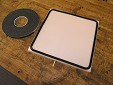
For this example, we will be building a vacuum clamping matrix that is 12" x 12". This is probably smaller than what the average user would want but it helps keep the concept simple. The matrix will be 2 x 2 (two rows and two columns of ball valves).
Begin with a 12" square piece of HDPE or other non-porous material. The HPDE is a great choice because it can but cut/drilled/shaped with ordinary power tools. The downside is that it can be expensive but it's probably worth the cost since the jig will last for very, very long time.
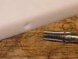
- Drill a 2" deep hole in the side edge of the HDPE using a 11/32" or 21/64" drill bit. Be sure to drill straight into the HDPE. A simple 90° jig against the back of the work piece will help keep the hole straight.
- Tap threads into this hole with a tapping tool. You need to screw in about 3/4 of tapping tool to get a snug fit.
- Remove the tapping tool and blow out any debris inside the hole. Then attach a 1/8" NPT brass barb fitting. If it doesn't go in smoothly, re-tap the hole and drive the tool in a bit further. This will expand the diameter of the threads and make it easy to install the brass fitting.
- Next, mark a place on the HDPE approximately 1.5" from the edge and directly over the hole from step 1.
- Using the mark as your guide, drill a 3/16" hole in the face of the HDPE directly over the 11/32" hole but only half way through the HDPE. Do not drill all of the way through it. This hole is the pathway for air from the brass fitting to the bottom side of the jig. The side with the hole from this step is the back side of the vacuum clamping jig.
- Now, flip the jig over so you are looking at the top side of the jig. Use the vacuum gasket tape to create a border around the top (face) side of the jig. It's best to use one continuous piece instead of four peices. You'll find the gasket tape goes around corners very easily if you remove the paperbacking while you are working with it. Be careful that you do not stretch the tape during application.
- When you have made a complete loop around the face of the jig, butt the ends of the gasket tape together tightly.
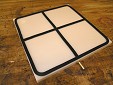
- Next, apply the vacuum tape to create the matrix. Since this will be a 2 x 2 matrix, apply a piece of gasket tape in the center of the HDPE so that it divides the face into two sections. Again, be sure to butt the edges of this new piece of gasket tape tightly against the edges of the perimeter gasket tape that was applied in the previous step.
- The next step is to divide each of the two vacuum sections into two sub-sections. Simply apply one piece of gasket tape across each section (perpendicular to the piece applied in step 9). Be sure to butt the edges closely together. This is critical.
- You are now ready to drill the holes on the jig for the ball valves. With a 13mm bit, drill holes in the center of each vacuum section. It is not critical that the holes be perfectly centered within the section. Drill completely through the HDPE.
- You can now apply gasket tape to the back side of the jig just as you did in step 7. For the back side of the jig, the perimeter seal is all that is needed. Do not divide the back side into sections.
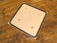
- Theoretically, the back of the jig needs support. When vacuum is applied, the gasket tape on the perimeter may cause the jig to have a slightly concave surface (when looking at the face side). To counteract this issue, simply apply small pieces of vacuum tape on the back of the jig in various areas as shown. These pieces will support the jig and will help to keep it flat during use.
- You can know attach the ball valves to the vacuum jig. The 13mm hole from step 11 will create a snug fit for the ball valves. You may need to use a hammer to get them seated into the holes.
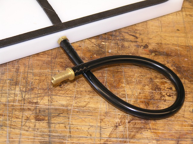
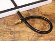
- The last step is to create a junction between the jig and your vacuum press.
If your vacuum press is one of the Excel™ systems, the connection to the vacuum clamping jig consists of a piece of vacuum tube and "tube adaptor". Attach the vacuum tube to the brass barb fitting on the jig. Then attach the tube adaptor to the tube. The lock-on connector from the vacuum press attaches to the tube adapter.
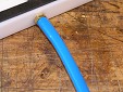
If your vacuum press is an auto-cycling model such as the Project: EVS, Project: EVS-2, or Project: V4 and you have the clamping add-on kit, you simply connect the vacuum matrix to the blue tubing that is included with the clamping kit.

The jig will vacuum itself onto your workbench during use. If you need to re-position the jig, you will have to turn off the vacuum system.
For maximum vacuum and jig efficiency, the vacuum clamping matrix should be used on a non-porous workbench and with non-porous clamping objects.
|
|

Step 1
Step 2

Step 3

Step 4
Step 6
Step 8

Step 10
Step 11

Step 12

Step 13
Step 14
for Excel™
vacuum presses
Step 14
for Auto-Cycling vacuum presses with optional clamping add-on
|
|